Tuesday, September 22, 2009

WiMAX Protocol Layers

Protocol layers are a hierarchical model of network or communication functions. The divisions of the hierarchy are referred to as layers or levels, with each layer performing a specific task. In addition, each protocol layer obtains services from the protocol layer below it and performs services to the protocol layer above it. The WiMAX system has four key layers; MAC convergence, MAC layer, MAC privacy and the physical layer.

MAC Convergence

The MAC convergence layer is a functional process within a communication device or system that adapts one or more transmission mediums (such as radio packet or circuit data transmission) to one or more alternative transmission formats (such as ATM or IP data transmission).

MAC Layer

The MAC layer is composed of one or more logical communication channels that are used to coordinate the access of communication devices to a shared communications medium or channel (microwave radio). MAC channels typically communicate the availability and access priority schedules for devices that may want to gain access to a communication system.

MAC Privacy

The MAC privacy layer is associated with authenticating and encrypting information over the communication link (inner coding).

Physical Layer

The physical layer performs the conversion of data to a physical transmission medium (such as copper, radio, or optical) and coordinates the transmission and reception of these physical signals. The physical layer receives data for transmission from an upper layer and converts it into physical format suitable for transmission through a network (such as frames and bursts). An upper layer provides the physical layer with the necessary data and control (e.g. maximum packet size) to allow conversion to a format suitable for transmission on a specific network type and transmission line.

Security Sub-Layer

A security sub-layer is the functional process within a communication device or system that performs access controls, identity validation and/or encryption of data.

Figure 1 depicts the multiple layers of WiMAX. The physical layer is responsible for converting bits of information into radio bursts while the MAC security layer is responsible for identifying the users (authentication) and keeping the information private (encrypting). The MAC layer is responsible for requesting access and coordinating the flow of information. The MAC convergence layer is used to adapt the WiMAX system to other systems such as ATM, Ethernet or IP data systems.

Figure 1: WiMax Protocol Layers

Saturday, September 19, 2009

WiMAX Radio Overview

A WiMAX radio channel is a communications channel that uses radio waves to transfer information from a source to a destination. It may transport one or many communication channels and communication circuits on a single RF channel.

WiMAX radio channels may operate within different frequency bands, have different radio channel bandwidths, dynamically change modulation types, use a variety of access technologies and other characteristics that allow WiMAX to reliably provide a variety of types of communication services.

The WiMAX radio systems can use a single carrier (SC) or multi-carrier (MC) transmission. Single carrier transmission is the use of a single carrier wave that is modified to carry (transport) all of the information. Multi-carrier is a communication system that combines or binds together two or more communication carrier signals (carrier channels) to produce a single communication channel. This single communication channel has capabilities (capacity) beyond any of the individual carriers that have been combined. When each of the carriers in a multi-carrier system is mutually independent (orthogonal) to each other, it is called orthogonal frequency division multiplexing (OFDM).

Figure 1 shows the key components of a basic WiMAX radio system. The major component of a WiMAX system include subscriber station (SS), a base station (BS) and interconnection gateways to datacom (e.g. Internet) and telecom (e.g. PSTN). An antenna and receiver (subscriber station) in the home or business converts the microwave radio signals into broadband data signals for distribution. In the example, a WiMAX system is being used to provide telephone and broadband data communication services. When used for telephone services, the WiMAX system converts broadcast signals to an audio format (such as VoIP) for distribution to IP telephones or analog telephone adapter (ATA) boxes. When WiMAX is used for broadband data, the WiMAX system also connects the Internet through a gateway to the Internet. The WiMAX system can reach distances of up to 50 km when operating at lower frequencies (2-11 GHz).

Figure 1: WiMax System

Thursday, September 17, 2009

Adaptive Antenna System (AAS) | Technologies

An adaptive antenna system allows a transmitter to focus radio beams to increase the transmission range, reduce interference and increase signal quality. When an AAS system is used to allow multiple users to communicate with the same transceiver (multiple beams), it is called spatial division multiple access (SDMA). SDMA technology has been successfully used in satellite communications for several years. In some SDMA systems, radio beams may dynamically change with the location of the mobile radio.

The WiMAX system is designed with AAS capability. To support AAS, it is necessary to supplement the medium access control (MAC) protocol with additional commands so that base stations can better monitor subscriber stations which may be operating in a narrow focused beam area. If the subscriber station were to move out of the focused beam area, the system could loose control of the subscriber station.

Figure 1 shows an example of a WiMAX adaptive antenna system (AAS). The cell site can focus radio signals using the same frequency to multiple devices within the same cell site. Focusing of the radio signal allows for an increase in the distance that a cell site can have when communicating with devices. Using AAS technology, the system can adapt the direction of the focused beam to a specific device as it moves throughout the coverage area.

Figure 1: WiMax Adaptive Antenna System

Tuesday, September 15, 2009

Diversity Transmission

Diversity transmission is the process of using two or more signals to carry the same information source between a transmitter and a receiver. Diversity transmission can use the physical separation of antenna elements (spatial diversity), the use of multiple wavelengths (frequency diversity) and the shifting of time (time diversity).

Protocols on the WiMAX system are designed to take advantage of diversity transmission options and to allow for the use of multiple input multiple output (MIMO) antenna systems. MIMO is the combining or use of two or more radio or telecom transport channels for a communication channel through the user of multiple antenna elements. The use of MIMO to combine alternate transport links provides for higher data transmission rates (inverse multiplexing) and increased reliability (interference control).

Transmission Diversity

Transmission diversity is the process of sending two or more signals from the same information source so a receiver can select or combine the signals to produce a received signal of better quality than a single transmitted signal.

Receive Diversity

Receive diversity is used to select or combine a received signal to yield a stronger signal quality level. Receive diversity uses two antennas that are physically separated vertically or horizontally.

Receiver diversity can compensate for radio signal fading that may occur on a single antenna, and may be performed by maximum ratio combining (MRC) or selection diversity. Maximal ratio combining is the process of combining the signals from two or more antenna elements to increase the level and quality of a received signal. Selection diversity is the process of selecting one antenna from a set of receiving antennas to increase the level or quality of a received signal.

Frequency Diversity

Frequency diversity is the process of receiving a radio signal or components of a radio signal on multiple channels (different frequencies) or over a wide radio channel (wide frequency band) to reduce the effects of radio signal distortions (such as signal fading) that occur on one frequency component but do not occur (or are not as severe) on another frequency component.

Temporal (Time) Diversity

Time diversity is the process of sending the same signal or components of a signal through a communication channel where the same signal is transmitted or received at different times. The reception of two or more of the same signal with time diversity may be used to compare, recover, or add to the overall quality of the received signal.

Spatial Diversity

Spatial diversity is a method of transmission or reception employed to minimize the effects of fading by the simultaneous use of two or more antennas spaced a number of wavelengths apart.

Antenna diversity is a form of spatial diversity that improves the reception of a radio signal by using the signals from two (or more) antennas to minimize the effects of radio signal fading or distortion. Antenna diversity typically requires the antennas to be spaced a number of wavelengths apart.

Space time coding is the adding of time information to transmission carriers to allow diversity operation by identifying and processing multiple carriers of the same signal that may arrive at different times and or from different locations.

Figure 1 shows different types of diversity transmission and reception. The antenna (spatial) diversity utilizes the distance between antennas to improve signal performance. Frequency (spectral) diversity transmits the same or related information on multiple frequency signals to reduce frequency selective fading. Time (temporal) diversity overcomes the challenges of burst distortion by allowing the same information signal to be received at different times.

Figure 1: Diversity Transmission

Sunday, September 13, 2009

Modulation | Technologies

Modulation is the process of changing the amplitude, frequency, or phase of a radio frequency carrier signal with the information signal (such as voice or data). The 802.16 system uses different types of digital modulation depending on a variety of transmission factors. The modulation types used in 802.16 systems include binary phase shift keying (BPSK), quadrature phase shift keying (QPSK) and quadrature amplitude modulation (QAM).

Binary Phase Shift Keying (BPSK)

Binary phase shift keying (BPSK) is a modulation process that converts binary bits into phase shifts of the radio carrier without substantially changing the frequency of the carrier waveform. The phase of a carrier is the relative time of the peaks and valleys of the sine wave relative to the time of an unmodulated “clock” sine wave of the same frequency. BPSK uses only twophase angles, corresponding to a phase shift of zero or a half cycle (zero or 180 degrees of angle). WiMAX uses BPSK modulation when a very robust signal is required.

Quadrature Phase Shift Keying (QPSK)

Quadrature phase shift keying (QPSK) is a type of modulation that uses 4 different phase shifts of a radio carrier signal to represent the digital information signal. These shifts are typically +/- 45 and +/- 135 degrees.

Quadrature Amplitude Modulation (QAM)

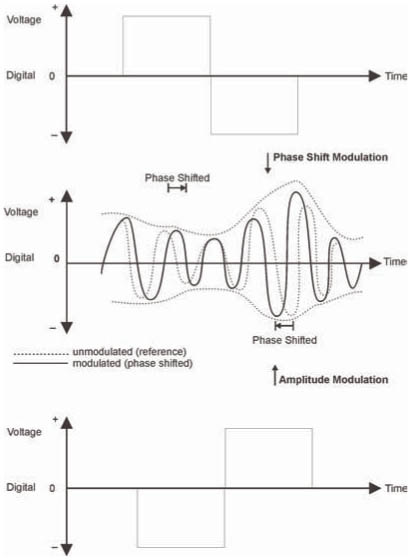
QAM is a combination of amplitude modulation (changing the amplitude or voltage of a sine wave to convey information) together with phase modulation. There are several ways to build a QAM modulator. In one process, two modulating signals are derived by special pre-processing from the information bit stream. Two replicas of the carrier frequency sine wave are generated; one is a direct replica and the other is delayed by a quarter of a cycle (90 degrees). Each of the two different derived modulating signals are then used to amplitude modulate one of the two replica carrier sinewaves respectively. The resultant two modulated signals can be added together. The result is a sine wave having a constant unchanging frequency while having an amplitude and phase that both vary to convey the information. At the detector or decoder the original information bit stream can be reconstructed. QAM conveys a higher information bit rate (bits per second) than a BPSK or QPSK signal of the same bandwidth, but is also more affected by interference and noise.

Figure 1 shows that amplitude and phase modulation (QAM) can be combined to form an efficient modulation system. One digital signal changes the phase and another digital signal changes the amplitude.

Figure 1: Quadrature Amplitude Modulation (QAM)

Adaptive Modulation

Adaptive modulation is the process of dynamically adjusting the modulation type of a communication channel based on specific criteria (e.g. interference or data transmission rate). WiMAX systems use adaptive modulation to ensure the modulation type matches the channel characteristics (signal quality level).

In general, the more efficient (data transmission capacity) the modulation type, the more complex or precise the modulation process is. The more precise the modulation process (smaller changes represent digital bits), the more sensitive the modulation is to distortion or interference. This usually means that as the data transmission rate increases, the sensitivity to interference intensifies. To help manage this process and ensure the maximum data transmission rate possible, 802.16 systems automatically change their data modulation types and data transmission rates (Autorate) based on the ability of the channel to transfer data. The 802.16 systems will usually try to send information at the highest data transmission rate possible. If the data transmission rate cannot be maintained, the 802.16 systems will attempt to transmit at the next lower data transmission rate. Lower data transmission rates generally use a less complex (more robust) modulation type.

Wednesday, September 9, 2009

Frequency Reuse | Technologies

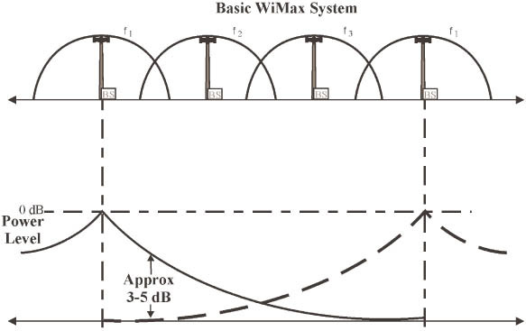
Frequency reuse is the process of using the same radio frequencies on radio transmitter sites within a geographic area that are separated by sufficient distance to cause minimal interference with each other. Frequency reuse allows for a dramatic increase in the number of customers that can be served (capacity) within a geographic area on a limited amount of radio spectrum (limited number of radio channels). Frequency reuse allows WiMAX system operators to reuse the same frequency at different cell sites within their system operating area.

The number of times a frequency can be reused is determined by the amount of interference a radio channel can tolerate from nearby transmitters that are operating on the same frequency (carrier to interference ratio).

Carrier to interference (C/I) level is the amount of interference level from all unwanted interfering signals in comparison to the desired carrier signal. The C/I ratio is commonly expressed in dB. Different types of systems can tolerate different levels of interference dependent on the modulation type and error protection systems. The typical C/I ratio for narrowband mobile radio systems ranges from 9 dB (GSM) to 20 dB (analog cellular). WiMAX systems can be much more tolerant to interference levels (possibly less than 3 dB C/I) when OFDM and adaptive antenna systems are used.

WiMAX systems may also reuse frequencies through the use of cell sectoring. Sectoring is a process of dividing a geographic region (such as a radio coverage area) where the initial geographic area (e.g. cell site coverage area) is divided into smaller coverage areas (sectors) by using focusing equipment (e.g. directional antennas).

Figure 1.20 shows how radio channels (frequencies) in a WiMAX communication system can be reused in towers that have enough distance between them.

Figure 1.20: WiMax Frequency Reuse

The radio channel signal strength decreases exponentially with distance. As a result, mobile radios that are far enough apart can use the same radio channel frequency with minimal interference.

Sunday, September 6, 2009

Orthogonal Frequency Division Multiple Access (OFDMA)

Orthogonal frequency division multiple access is the process of dividing a radio carrier channel into several independent sub-carrier channels that are shared between simultaneous users of the radio carrier. When a mobile radio communicates with an OFDMA system, it is dynamically assigned a specific sub-carrier channel or group of sub-carrier channels within the radio carrier. By allowing several users to use different sub-carrier channels, OFDMA systems increase their ability to serve multiple users and the OFDMA system may dynamically allocate varying amounts of transmission bandwidth based on how many sub-carrier channels have been assigned to each user.

As demonstrated in Figure 1, the WiMAX system allows more than one simultaneous user per radio channel through the use of orthogonal frequency division multiple access (OFDMA). The WiMAX radio channel can be divided into multiple sub-carriers and that the sub-carriers can be dynamically assigned to multiple users who are sharing a radio carrier signal. Finally, the data rates that are provided to each user can vary based on the number of subcarriers that are assigned to each user.

Figure 1: Orthogonal Frequency Division Multiple Access (OFDMA)

Thursday, September 3, 2009

Orthogonal Frequency Division Multiplexing (OFDM)

Some of the key technologies used in WiMAX systems include orthogonal frequency division multiplexing, frequency reuse, adaptive modulation, diversity transmission and adaptive antennas.

Orthogonal Frequency Division Multiplexing (OFDM)

OFDM is a process of transmitting several high speed communication channels through a single communication channel using separate sub-carriers ( frequencies) for each radio channel. The use of OFDM reduces the effects of multi-path and delay spread, which is especially important for lower frequencies and near line of sight (NLOS) transmission.

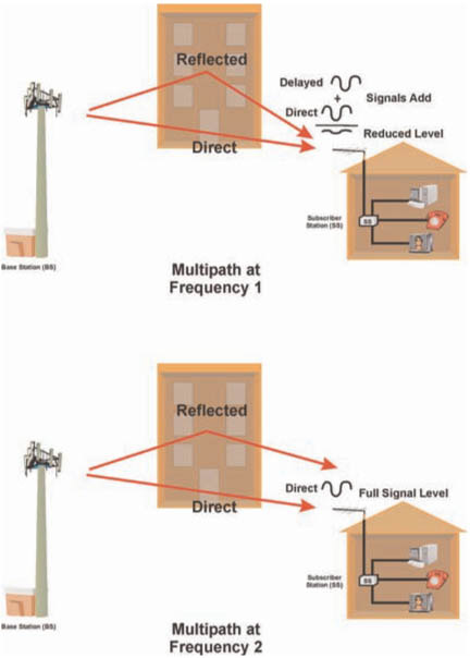
Multi-path propagation is the transmission of a radio signal which travels over two or more paths from a transmitter to a receiver. Multi-path transmission can cause changes in the received signal level as delayed signals can either add or subtract from the received signal level. Multi-path is not usually a challenge on systems that use higher frequencies as these systems tend to use highly directional (high-gain) antennas for direct line of sight transmission.

Multi-path propagation is frequency dependent meaning that the multiple paths radio signals travel will vary depending on its’ frequency.

Figure 1illustrates how a transmitted signal may travel through multiple paths before reaching its destination. In this example, the same signal is reflected off an office building where it is received by the subscriber device. The reflected signal is delayed (travels a longer path) and subtracts from the direct signal resulting in a dead spot (fade) at the receiver. Furthermore, mutli-path propagation is sensitive to frequency and that distortion occurs at different points when other frequencies are used. When a different frequency is used, the reflected signal is redirected and it does not subtract from the direct signal.

Figure 1: Multi-path Propagation

For a wide radio channel that is divided into several sub-carriers, each subcarrier channel operates at a different frequency and can have different transmission characteristics than other sub-carriers. Because multiple sub-carriers are typically combined for a single subscriber, this can reduce the effects of multi-path fading.

The use of multiple sub-carriers also has the effect of reducing the symbol rate, which can reduce the effects of delay spread. Delay spread is a product of multi-path propagation where symbols become distorted and eventually overlap due to the same signal being received at a different time. It becomes a significant problem in mountainous areas where signals are reflected at great distances. Delay spread can be minimized by either using an equalizer to adjust for the multi-path distortions or to divide a communication channel into sub-carriers (e.g. OFDM) where each sub-carrier transfers data at a much slower data transmission rate thereby reducing the effects of delay spread.

Figure 2 demonstrates how OFDM divides a single radio channel into multiple coded sub-channels. A high-speed digital signal is divided into multiple lower-speed sub channels that are independently from each other and can be individually controlled. The OFDM process allows bits to be sent on multiple sub channels. The channels selected can be varied based on the quality of the sub channel. In this figure, a portion of a sub channel is lost due to a frequency fade. As a result of the OFDM encoding process, the missing bits from one channel can be transmitted on other channels.

Image from book Figure 2: Orthogonal Frequency Division Multiplexing (OFDM)
Related Posts with Thumbnails