Saturday, October 31, 2009

Payload Header Suppression (PHS)

PHS is the process of removing or blocking the transfer of packet header information. Payload header suppression is usually performed to remove redundant or unnecessary information such as a source and destination address that does not change for packets that are sent on a fixed communication link.

The PHS process begins with requesting a PHS session and negotiating the parameters or rules on how PHS will operate during the session to determine which bits and how many bits of the header may be altered or removed. PHS suppression operation may include the removal of address bits and other control information (such as IP address port number) that may be part of the header.

The header information is stored at the sending end and receiving ends to allow for the detection and removal of the header (the sending end) and the reinsertion of the header at the receiving end. The header is removed by using a payload header suppression mask (PHSM). The PHSM is a code or binary sequence that is used to allow, block, or modify specific bits in a header to create the information that will be transmitted. To allow the receiver to recreate information that is located within the header that sequentially changed, a payload header suppression index (PHSI) is used. The PHSI is an incremental value that is used to identify the sequence of payload header suppression messages.

When the compressed packet arrives at the receiver, the packet header information is recreated and inserted into the packet so the original data packet (header and data) is completely recreated.

Figure 1 shows how PHS can be used to increase the data transmission rate through a communication channel. An IP communication session that occurs over an unchanging (circuit switched) wireless data link can use PHS to increase the efficiency (higher data throughput) by removing redundant packet header data. When an IP session is setup over a circuit switched connection, the system first identifies that PHS will be used. The system then negotiates for which parts of the header will be changed or removed during transmission (establishes PHS rules). The negotiation associates (maps) the IP communication system to the data link connection and stores the unchanging information at each end of the communication link (the header mask). For each IP packet that is received, the IP address information and some control information is removed prior to transmitting the packet on the data link (packet compression). When the compressed packet arrives at the receiver, the IP address and packet header information is re-inserted on the packet so the IP data packet is completely recreated.

Figure 1: Payload Header Suppression

Wednesday, October 28, 2009

Channel Measurement Reports

Channel measurement reports are groups of channel quality measurements that are sent from one radio device (such as a subscriber station) to another radio device (such as a system base station transceiver) that may be used to assist and adjust the radio transmission parameters (such as modulation type and RF power level) between the radio devices. Channel measurement reports are typically sent periodically to allow the base station or system to determine how the channel quality is changing to help it make decisions on channel modulation and coding types. The WiMAX system channel measurement reports include; radio signal strength indicators (RSSI), and channel to interference and noise ratio (CINR).

RSSI is the approximate level of a received signal captured by the radio device. Carrier to interference and noise ratio is a comparison of the information-carrying signal power to the interference and noise power in a system.

Monday, October 26, 2009

RF Power Control

RF power control is a process of adjusting the power level of a mobile radio as it moves closer and further away from a transmitter. RF power control is typically accomplished by sensing the received signal strength level to determine the necessary power level adjustments. The base stati then sends power control messages to the mobile device to increase or decrease the mobile device’s output power level. The WiMAX system uses various forms of RF power control including open loop power control and closed loop power control.

Open loop power control is a process of adjusting the transmission power level for the subscriber station using the received power level. Open loop power control in the WiMAX system is used when the subscriber station initially attempts to accessing the system. When accessing the WiMAX system, the subscriber station calculates its’ initial transmit power level using parameters that are broadcasted from the WiMAX system along with the signal strength that it receives. The smaller the signal strength it receives, the larger the initial transmit power level it uses when accessing the WiMAX system.

Closed loop power control is a process of adjusting the transmission power level for the mobile radio using the power level control commands from another transmitter that is receiving its signal (e.g. from a radio base station). The WiMAX system uses closed loop power control to continually adjust the transmitter level of the subscriber station as it moves, or as the signal level varies (such as when signal fading occurs or when obstructions move).

Figure 1 reveals how the radio signal power level output of a subscriber station is first determined by the received signal power level and is then adjusted by commands received from the base station to reduce the average transmitted power from the subscriber station. This lower power reduces interference to nearby cell sites and helps to ensure the signal level received by the base station from all the subscriber stations is approximately the same. As the subscriber station moves closer to the base station, less power is required from the subscriber station and it is commanded to reduce its transmitter output power level. The base station transmitter power level can also be reduced.

Figure 1: WiMax Power Control

Sunday, October 25, 2009

Dynamic Frequency Selection (DFS)

Dynamic frequency selection is a process that allows devices or users to request, select or change an operating frequency at various times. Dynamic frequency selection involves sensing and assigning communication channels (such as radio frequencies) to transmitters (such as a radio base station) as they are required. The use of dynamic frequency selection in a WiMAX system allows for interference avoidance.

Interference avoidance is a process that adapts the access channel sharing method so that the transmission does not occur on specific frequency bandwidths. Using interference avoidance, devices that operate within the same frequency band and within the same physical area can detect the presence of each other and adjust their communication system to reduce the amount of interference caused by each other. This reduced level of interference increases the amount of successful transmissions therefore increases the efficiency and increases the overall data transmission rate. Dynamic frequency selection is used by WiMAX systems that operate in unlicensed frequency bands.

Friday, October 23, 2009

Ranging (Dynamic Time Alignment) | WiMAX Radio

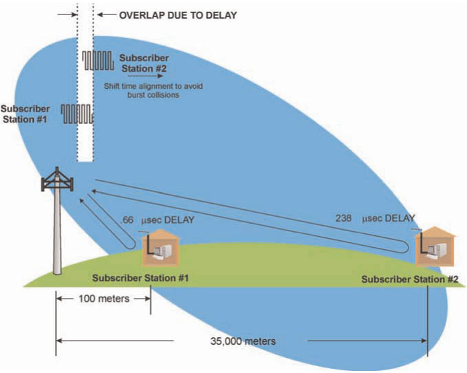
Ranging is a dynamic time alignment process that allows a radio system base station to receive transmitted signals from mobile communication devices in an exact time slot, even though not all mobile communication devices are the same distance from the base station. Ranging keeps different mobile device transmit bursts from colliding or overlapping. Ranging is necessary because subscriber stations may be moving or have been moved, and their radio waves’ arrival time at the base station depends on their changing distance from the base station. The greater the distance, the more delay in the signal’s arrival time. Transmission delay is approximately 3 microseconds per km (or 5 microseconds per mile). To perform time alignment, a subscriber station can advance or delay its transmission timing relative to the reference message that it receives on the downlink channel.

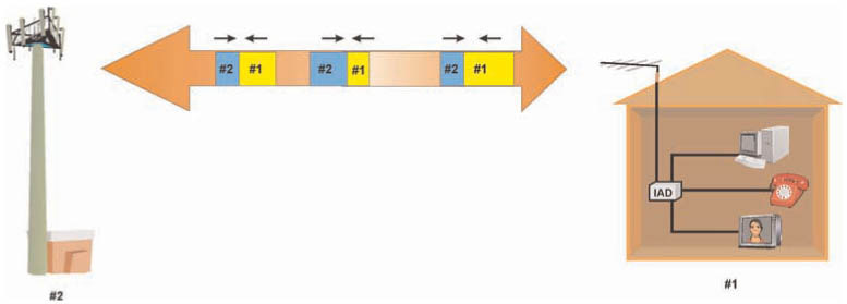
Figure 1: WiMax Adaptive Time Division Duplex (ATDD) Transmission

The WiMAX system uses two types of ranging: initial ranging and periodic ranging. During initial ranging, the WiMAX subscriber station transmits a brief ranging request message that allows the system to send back a ranging response message with the amount of timing offset that the subscriber station must use when it begins transmitting. After the subscriber station has attached to the system, the base station will continually send time alignment messages (periodic ranging) to the subscriber station to adjust (fine tune) its timing advance as it moves in the radio coverage area.

Initial ranging is the process of time aligning with a communication system before establishing a communication session. The initial ranging process involves synchronizing to an incoming transmission channel, sending a request at a particular time interval relative to the received channel and obtaining a response that allows for the time synchronization with the device or system.

Periodic ranging is the process of continuous time alignment with a communication system during a communication session. The periodic ranging process involves maintaining synchronization with an incoming transmission channel, periodically transmitting messages (such as sending user data) and receiving time alignment information from the other device or system.

If the subscriber station is continually communicating with the base station (receiving or transmitting data), the system can sense changes in the timing and send time alignment messages along with other packets of data to the subscriber station. If a significant amount of time has elapsed since a subscriber device has communicated with the system, the BS must initiate polling requests to reinitiate the ranging process.

Figure 2 shows how the relative transmitter timing in a subscriber station (relative to the received signal) is dynamically adjusted to account for the combined receive and transmit delays as the WiMAX radio is located at different distances from the base station antenna. In this example, the subscriber station uses a received burst to determine when its burst transmission should start. As the subscriber station moves away from the tower, the transmission time increases therefore causing the transmitted bursts to slip outside its time slot when it is received at the base station (possibly causing overlap to transmissions from other radios.) When the base station receiver detects the change in slot period reception, it sends commands to the subscriber station to advance its relative transmission time as it moves away from the base station and to be delayed as it moves closer.

Figure 2: WiMax Ranging

Tuesday, October 20, 2009

Duplex Transmission | WiMAX Radio

Duplex transmission is the simultaneous transmission of two information signals that allows simultaneous (or near simultaneous) 2-way communication. The WiMAX system can use frequency division duplex (FDD), time division duplex (TDD) or half frequency division duplex (H-FDD).

FDD is the process of simultaneously allowing the transmission of information in both directions via separate frequency bands. When using FDD, each device transmits on one frequency while listening on a different one.

TDD refers to the process of allowing two way communications between two devices by time-sharing. When using TDD, device 1 transmits while device 2 listens for a short period of time. After the transmission is complete, the devices reverse their role so device 1 becomes a receiver and device 2 becomes a transmitter. The process continually repeats itself so data appears to flow in both directions simultaneously.

H-FDD is a process that allows for two-way communications between two devices through the combination of frequency division and time sharing. When using H-FDD, device 1 transmits on one frequency while the device 2 listens for a short period of time on that frequency. After the transmission is complete, the devices reverse their roles and device 2 transmits on a different frequency and the other device listens for a short period of time on that frequency. The process continually repeats itself so data appears to flow in both directions simultaneously. The use of H-FDD systems allows for the simplification of radio design as the transmitters and receivers in the same unit are separated in both frequency and time so a duplex filter is not required.

As shown in Figure 1, the WiMAX system may use three types of duplexing: frequency division duplex (FDD), time division duplex (TDD) and half frequency division duplex (H-FDD). FDD allows the transmission of information in both directions at the same time by using separate frequency bands ( frequency division). Half frequency division duplex uses different frequencies for transmission but does not allow transmission and reception at the same time.

Figure 1: WiMax Duplex Transmission

When operating in time division duplex mode, WiMAX devices require reserved time periods to allow for transmission time (guard time) and to allow the device to transition between receive and transmit modes (transition gap).

Guard time is an amount of time that is allocated within a single time slot period in a communication system to help ensure variable amounts of transit times (e.g. from close and distant transmitters) do not cause overlap ( collisions) between adjacent time slots. Transmission of information does not occur within the guard period.

Receive-transmit transition gap is the amount of time that is allocated between the reception of a packet and transmission of a packet in a time division duplex (TDD) system. Transmit-receive transition gap is the amount of time that is allocated between the transmission of a packet and the reception of a packet in a time division duplex (TDD) system.

WiMAX systems have the capability to dynamically change the amount of bandwidth that is transmitted in either direction through a process called adaptive time division duplex (ATDD). ATDD is a process of allowing two way communications between two devices by time sharing on the same communication channel (e.g. the same frequency) and the amount of transmission rate or time that is used by each device can dynamically change.

Figure 1 illustrates how the WiMAX system can use adaptive time division duplex transmission to vary the amount of bandwidth that is transferred in either direction. A base station initially sends data at a high rate. However, after the user has received the data, the base station begins to send a response at a high rate. The time periods allocated for transmission on the downlink and uplink continually vary to allow for variable data transmission rates.

Saturday, October 17, 2009

Channel Coding | WiMAX Radio

Channel coding is a process where one or more control and user data signals are combined with error protected or error correction information. The WiMAX system channel coding processes include error correction coding, interleaving and randomization.

Error Correction Coding

Error correcting codes are additional information elements that are sent along with a data signal that can be used to detect and possibly correct errors that occur during transmission and storage of the media. Error correction codes conform to specific rules or formulas to create the code from the data that is being sent. Error correction codes require an increase in the number of signal elements that are transmitted which increases the required data transmission rate. The WiMAX system can use a variety of error coding methods including Reed Soloman coding, convolutional coding (optional) and block turbo coding (optional).

Interleaving

Interleaving is the reordering of data that is to be transmitted so that consecutive bytes of data are distributed over a larger sequence of data to reduce the effect of burst errors. The use of interleaving greatly increases the ability of error protection codes to correct for burst errors. Many of the error protection coding processes can correct for small numbers of errors, but cannot correct for errors that occur in groups. The WiMAX system uses interleaving to map data onto non-adjacent sub-carriers to help overcome the effects of frequency selective (e.g. multi-path) distortion.

Randomization

Randomization is a process that rearranges data components in a serial bit sequence to statistically approximate a random sequence. For communication systems, randomization involves using a known randomization code or process in the transmitter and using the same code to decode the randomized sequence at the receiver.

The WiMAX system uses a pseudo-random binary sequence (PRBS) randomization process that ensures that there are no long sequences of bits that would cause the modulator to produce a high peak to average power ratio (PAPR) signal. PAPR is a comparison of the peak power detected over a period of sample time to the average power level that occurs over the same time period. A high PAPR would require the use of a more linear RF amplifier assembly increasing cost and decreasing power conversion efficiency (e.g. shorter battery life).

Wednesday, October 14, 2009

Channel Descriptors | WiMAX Radio

Channel descriptor is a set of information parameters that describe the characteristics associated with a communication channel. The use of a channel descriptor can permit more accurate and successful reception and decoding of information that is sent on a communication channel.

The WiMAX system periodically sends (broadcasts) channel descriptors on the downlink channel to allow the subscriber stations to understand how to decode and transmit messages. Channel descriptors provide information about the uplink and downlink channels.

The downlink channel descriptor contains a downlink frame prefix that provides the information to the receiver about the frame structure of the downlink channel and a downlink map (DL-MAP) that defines what information will be transmitted. The DL-MAP contains a downlink interval usage code (DIUC) that defines when information will be transmitted on the downlink and what formats it is supposed to use (burst profile).

The uplink channel descriptors contain an uplink map (UL-MAP) message that defines when a subscriber station is allowed to transmit on the uplink and what formats it is supposed to use (burst profile). The UL-MAP contains an uplink interval usage code (UIUC) that defines when a subscriber station is allowed to transmit on the uplink and what formats it is supposed to use (burst profile).

Figure 1 demonstrates how the WiMAX system uses channel descriptors to define the allocated times and burst types that are used on WiMAX radio channels.

Figure 1: WiMax Channel Descriptors

Sunday, October 11, 2009

Radio Packets (Bursts) | WiMAX Radio

A radio packet is a short transmission (a burst) of information that occurs on a radio channel. Radio bursts contain reference sequences (preamble and possible a midamble), control information and payload of data.

The radio packet burst may have different types of radio characteristics such as modulation type, error coding, preamble length and transmission guard time periods. The combination of these characteristics is called the burst profile.

A burst set is a single transmission (RF packet) that contains a preamble along with one or more bursts of information. The bursts of information contained within the RF packet may have different modulation and coding types. A burst frame is the complete set of information that is contained in a transmission burst.

The bursts within a burst set are sequenced according to their modulation complexity. Bursts with lower complexity modulation types are located at the beginning of the radio packet. Bursts that follow can use modulation types with higher complexity (e.g. QPSK, QAM). This allows subscriber stations to receive and decode all the bursts up to the burst with the highest modulation type it can receive.

RF bursts start with a sequence of bits (a preamble) that the receiving device can recognize and lock onto. Once the receiving device locks onto the preamble, it knows where to find the rest of the packets.

For longer RF bursts, midamble sequences may be periodically inserted to assist receivers in the decoding of bursts. A midamble is a sequence of bits that the receiving device can recognize and lock onto to help decode the bits surrounding the midamble. Increased mobility (speed) can be tolerated when preambles and midambles are sent more frequently.

Burst profiles may continually change on a WiMAX system. Subscriber stations can send burst profile change request messages that define a desired new burst profile characteristic (such as modulation type or error coding). The request may be a result of an increase in the error rate using an existing burst profile.

Data packets may be inserted (embedded) within the payload of a single RF burst, they may be divided (fragmented) so they can be distributed over several radio packet bursts or multiple small packets may be combined (packed) into the payload.

Figure 1 depicts an example of a WiMAX radio packet which is made of a preamble and a set of bursts. The figure shows that the modulation type of the burst starts simple (BPSK) and gets more complex as additional bursts follow.

Figure 1: WiMax RF Packets

Thursday, October 8, 2009

Medium Access Control Protocol Data Units (MAC PDUs)

Medium access control protocol data units are a package of data (group of data bits) that contain header, connection address and data protocol information that is used to control and transfer information across a type of medium (such as a radio channel). The WiMAX system MAC PDUs contain a header, which holds the connection identifier along with control information. MAC PDUs may also have payload of data and error checking bits (CRC) bits after the header (e.g. user data). A MAC PDU header contains a header type, encryption control field, payload type and error checking (CRC) code.

A header type is a data field within the packet header that indicates the type of the header. The header type typically indicates the field format of the header and/or sub-headers that are part of the data packet.

Encryption control is the transferring parameters or sending of signaling messages in a data field within the header of a data packet that indicates encryption is used and possibly the type of encryption that is used. An encryption control field in a header typically indicates the payload of the data packet is encrypted.

Payload type is a data field within a packet header that indicates the format of the payload of data including any sub-headers

A cyclic redundancy check indicator is a data field within a packet header that indicates if and how a CRC error check code is used for the packet of data.

Encryption key sequence is an index value that is used to identify the location of a data packet within a sequence of packets to enable the decryption of the packet.

A length field is a data field within a packet header that holds a number or value that indicates the length of a data packet or a block of data.

A connection identifier is a unique name or number that is used to identify a specific logical connection path in a communication system. For the WiMAX system, the connection identifier is a 16 bit code.

A header check sequence is a calculated code that is used to check if the bits within a header have been received correctly during transmission.

Figure 1 shows the typical construction of generic WiMAX medium access control packet. This diagram shows that generic WiMAX MAC data packets contain addressing and controlling information and the payload can have variable length. This diagram shows that the MPDU header is 6 bytes long and that the header type indicator is used to determine which, if any, subheaders may be used.

Figure 1: WiMax MAC PDU

Monday, October 5, 2009

Addressing | WiMAX Radio

Each WiMAX radio is configured at the factory with a unique 48 bit medium access control address (MAC address) as identified in IEEE standard 802-2001. The first few bits of the MAC address indicate the manufacturer of the device. The remaining bits are a unique serial number of the device. While it is possible for a single subscriber device to have more than one 48 bit physical MAC address, most devices have a single MAC address.

The 48 bit MAC address is not part of the transmitted packet (MPDU). Instead, the device is identified by a 16 bit connection identifier (CID) that is assigned after the device has connected to the system. The MAC address is transferred during the device registration or authentication process to allow the system to identify the specific user. A single WiMAX device may contain 1 or more globally unique MAC addresses.

Each WiMAX device typically has several CIDs assigned. Some of the CIDs are used for controlling information and some are used to identify user data transmission channels (traffic channels).

The 16 bit CID is used to identify and categorize traffic (a maximum of 65,535 CIDs can exist per RF channel). Some CIDs are pre-assigned for specific functions (such as initial ranging) and others are unique to a specific connection.

A single CID may be shared by several services (logical channels). Each of these channels is a service flow and is identified by a service flow identifier (SFID).

To reduce the amount of overhead on a WiMAX radio channel (bits dedicated for control purposes), a shortened version of a CID (called a reduced connection identifier) may be used. A reduced connection identifier (RCID) can be 11, 7 or 3 bits long.

Saturday, October 3, 2009

Radio Propagation | WiMAX Radio

Radio propagation is the process of transferring a radio signal ( electromagnetic signal) from one point to another point. Radio propagation may involve a direct wave (space wave) or a wave that travels along the surface (a surface wave). Radio propagation characteristics typically vary based on the medium of transmission (e.g. Air) and the frequency of radio transmission. WiMAX systems may be operated as line of sight (direct transmission path) or non line of sight (indirect transmission path) systems.

WiMAX systems are typically designed with a radio link budget. A link budget is the maximum amount of signal losses that may occur between a transmitter and receiver to achieve an adequate signal quality level. The link budget typically includes cable losses, antenna conversion efficiency, propagation path loss, and fade margin.

Due to transmission impairments, a fade margin is budgeted in a communication link. Fade margin is the amount of signal loss, usually expressed in decibels, that a radio signal in a communication path is anticipated to change (or budgeted to change). This helps to ensure that typical signal fading periods do not result in a lower than expected quality of service.

One of the key types of signal fades that occur on microwave systems is a rain fade. A rain fade is the signal loss that results from signal absorption and scattering in water droplets (rain).

Line of Sight (LOS)

Line of sight (LOS) is a direct path in a wireless communication system that does not have any significant obstructions. WiMAX systems that operate in the 10-66 GHz range are LOS systems.

Non Line of Sight (NLOS)

Non line of sight (NLOS) is a wireless communication system that does not have a direct path (can have significant obstructions) between the transmitter and receiver. NLOS systems can use radio signals for transmission.

Figure 1 shows how non line of sight (NLOS) radio propagation can allow a radio signal to reach its destination in congested areas. A radio tower is transmitting through an urban area which does not allow a radio signal to travel a direct path from the tower to the receiver. Accordingly, multiple alternate paths are reflected off a building to reach its destination. A main signal (shortest reflected signal) and another signal (delayed signal) become part of the received signal.

Figure 1: Near Line of Sight Radio Propagation
Related Posts with Thumbnails